Article Text

Summary
In 2018, the Fédération Internationale de l’Automobile introduced the halo frontal cockpit protection system into Formula 1. While extensive testing was conducted to confirm that the halo protects the driver from contact, the halo’s effect on the driver during overtaking was not tested prior to its introduction. Here, we describe the effect of a halo-type structure on the neck muscle activity of one of the authors, a national-level amateur racing driver, during on-track simulations designed to practise overtaking. We found that the halo-type structure caused an increase in the rates of fatigue and workloads of sternocleidomastoid and cervical erector spinae. The results suggest that the driver adopted a forward and right laterally flexed head position, presumably to clear the central pillar from his visible field. This has the potential to increase compressive loading of the cervical spine and affect the ability to use visual cues during steering manoeuvres.
- statistics and research methods
- sports and exercise medicine
This is an open access article distributed in accordance with the Creative Commons Attribution Non Commercial (CC BY-NC 4.0) license, which permits others to distribute, remix, adapt, build upon this work non-commercially, and license their derivative works on different terms, provided the original work is properly cited and the use is non-commercial. See: http://creativecommons.org/licenses/by-nc/4.0/
Statistics from Altmetric.com
Background
The deaths of Ayrton Senna and Roland Ratzenberger at the 1994 San Marino Grand Prix were a watershed moment for Formula 1. The safety measures enacted largely because of the review which followed their deaths, but also due in no small part to efforts of Sid Watkins, resulted in something of a golden period in Formula 1 safety. In 2015, the Formula 1 community was stunned by the death of Jules Bianchi following a catastrophic head injury suffered during the 2014 Japanese Grand Prix. While the cause of Bianchi’s accident may be debatable, the mechanism of his injury was clear; a high-speed impact to his head. In the wake of Bianchi’s death and several other serious incidents involving impacts to or near-misses with the drivers’ heads; the Fédération Internationale de l’Automobile (FIA) introduced the halo frontal cockpit protection system for the 2018 Formula 1 season.1 The halo is designed to mitigate the risk of injury to the driver from: car-to-car contact, car-to-environment contact and external objects.2 An extensive retrospective analysis of accidents involving contact with the driver conducted by the FIA suggests that the halo will significantly mitigate the risk of cars and other objects in the environment from entering the cockpit.1 However, it remains unclear what effect the halo will have on the driver prior to impact. Verbal feedback provided by the drivers following installation laps and solo practice sessions indicates that the halo will not adversely affect visibility.1 However, subjective feedback does not address the effect of the halo on non-conscious processes. Nor do practice laps necessarily represent key tasks undertaken during racing such as overtaking. This is because vehicles typically do not come into close proximity and compete for track position during practice.
Successful overtaking requires drivers to avoid colliding with the car they are overtaking. Visually tracking and avoiding collisions with other vehicles while travelling at high speeds relies on the accurate representation of spatial structure which is perceived non-consciously via information sourced by the peripheral visual system.3–7 Because head posture is critical to steering control,8 if the halo influences a driver’s head posture, this could lead to navigational errors and affect their ability to avoid collisions. Moreover, the combination of head postures closer to end range of motion and high levels of neck muscle activation have been suggested to influence the pathomechanics of neck injury in high-g environments.9
Here, we report a unique case of the effect of a ‘halo-type’ structure on the activation pattern of one driver’s neck muscles during overtaking training. Annual assessment of neck muscle function using electromyography (EMG) is a key part of our continuous driver skill training programme. The resulting data are used to plan each driver’s skills training programme for the upcoming racing season. During the assessment, the vehicle is set up in accordance with any upcoming modification to the technical specifications which might reasonably impact on the drivers’ skill performance to ensure their training programme matches the constraints of racing as closely as possible. Because the FIA has stated that they intend to mandate the halo for all FIA open-cockpit championship,1 on-track simulations were run both with and without a ‘halo-type’ structure fitted to the cockpit to guide the driver’s neck training programme. The purpose of the halo-type structure was to provide a training stimulus to prepare the driver for the potential impact of the central pillar on collision avoidance during overtaking.
Case presentation
This case is a follow-up to a previous case reported in BMJ Case Reports, ‘The effect of a halo-type structure on neck muscle activation of an open-cockpit race car driver training under qualifying conditions’,10 which reported the effect of a halo-type structure during a single-car qualifying session. This case reports the effect of a halo-type structure on one of the authors, a 70-year-old man with more than 10 years experience in national-level open-cockpit (Formula) car racing, during a two-car race. The same custom fabricated halo-type structure was used. The horizontal hoop was mounted above the level of the driver’s head. It extended 812 mm forwards from the vehicle’s main roll bar to a central pillar which was mounted to the front roll bar. The central pillar was swept back at an angle of 53°. To mimic the halo, a non-structural triangular section was fitted at the junction of the horizontal hoop and the central pillar. The triangular section was 113 mm wide at the top tapering to 17 mm at the base and had a side length of 128 mm.
Investigations
Testing was conducted on a 4 km long, 19-corner, private race track. The race car used was the driver’s own race prepared Formula Mazda. The activation patterns of the driver’s left and right sternocleidomastoid (LSCM, RSCM) and the left and right cervical erector spinae (LCES, RCES) were measured using wireless surface EMG sensors (Delsys, Trigno IM, Boston, Massachusetts, USA) with the data recorded on the manufacturer supplied data logger. These measurements were synchronised to track position using a 10 Hz Global Positioning System (GPS) tracking unit (Catapult Optimeye S5, Catapult Sports, Docklands, Australia) mounted with the EMG data logger in the cockpit of race car. The driver’s head and neck safety equipment included a Head And Neck Support (HANS) device and a helmet meeting the FIA 8860 standard. Hence, sensor sites were chosen that afforded the assessment of muscles involved in the movement of the driver’s head in all three cardinal planes without impacting on his normal head position. Sensors were sited in accordance with the recommendations of the Surface ElectroMyoGraphy for the Non-Invasive Assessment of Muscles project for the placement of measuring electrodes.11 Muscle activity was recorded in millivolts at a rate of 1111 Hz. The sensor sites were marked with indelible ink so that the sensors could be located identically across driving sessions.
The driver completed two training simulations devised to practise the task of overtaking delivered in a cross-over design. The driver’s task in both simulations was to attempt to overtake the car in front at each corner without fully completing the manoeuvre. Only the two vehicles were present on the track during the simulations. For the first simulation, the driver’s car was not fitted with a halo-type frontal cockpit protection device. Four days later, the driver completed the second simulation with a mock-up of the halo-type frontal cockpit system fitted to the cockpit. The mock-up was designed to model the obstruction to the driver’s vision of the car ahead caused by the halo’s central pillar. The driver did not drive or engage in strenuous physical activity during the 3-day break between simulations.
Both simulations followed the same sequence. The driver was strapped into his car in the pits. Then the EMG and GPS data loggers were activated and synchronised by a sequence of taps. The driver then exited the pits and drove a set of 13 consecutive laps in a counter-clockwise direction (11 left- hand and 8 right-hand corners). The set of 13 laps consisted of 2 warm-up laps followed by 10 full-pace ‘flying laps’ then a cool-down lap. The driver completed the set of 13 laps in approximately 18 min. The driver then returned to pits, turned around and immediately re-existed the pits and drove a further set of five ‘flying laps’ and a cool-down lap in the opposite direction (clockwise). The driver completed the additional set of six laps in approximately 9 min. The driver was blinded to which set of laps (counter-clockwise or clockwise) would be used for the analysis.
Measures of muscle load and fatigue were modelled from analysis of the time-dependent median frequency of the EMG power spectrum. First, the raw EMG data were processed using Delsys EMGworks. The raw EMG recordings for each of the four sessions were trimmed to the initial 10 flying laps based on the GPS lap-time and position data. The trimmed EMG data were then bandpass filtered with a fourth order Butterworth filter with corner frequencies of 20 Hz and 500 Hz. The median frequency of the power spectrum was calculated using a short-time Fourier transform with a window length of 0.125 s and a window overlap of 0.0625 s. Median frequency data were then normalised to a percentage of the maximum median frequency per muscle per test and 0–1 time normalised. Only the data from the overtaking simulations are presented here.
Separate mixed-effects growth models were used to compare normalised median frequency (NMF) of each muscle across the two simulations. A progressive modelling strategy was used.12 This strategy involves testing a series of models and determining which model fits the data better based on the results of a X2 likelihood ratio test. This strategy is recommended when using growth models to examine rates of change over time.13 First, an unconditional linear growth model was fitted to the data to examine whether NMF varied with time across the 10 laps. If the linear model growth suggested that NMF was time dependent, a quadratic trend was added to the model to examine whether the rate of change NMF accelerated or decelerated. If the quadratic trend suggested that the rate of change was not constant, a cubic trend was added to the model to examine whether the influence of quadratic trend diminished or increased over time. Conditional models were then formed based on the linear, quadratic or cubic growth model that fitted the data best according to the results of each model and the X2 likelihood ratio tests. The conditional models were designed to investigate whether NMF was related to the halo-type structure (ie, halo, no halo). Two parameters were measured, muscle contractile level (workload) and the rate of muscle fatigue (fatigue). The y-intercept of the fitted growth curve, which corresponds to initial NMF, was used as an index of workload at the beginning of the race before fatigue modified the EMG signal.14 15 An increase in workload results in an increase in instantaneous NMF.16 The slope of the fitted growth curve was used as an index of muscle fatigue.14 15 Fatigue results in a downward shift in NMF which results in a negative slope.14–16
Outcome and follow-up
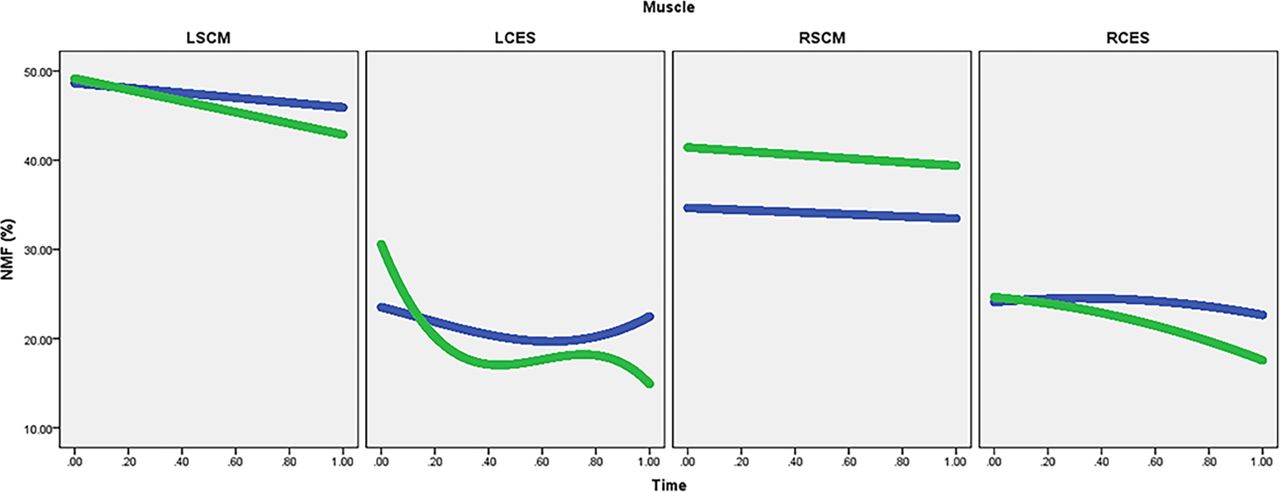
Figure 1 shows the driver’s head position in sequential images taken on corner entry, mid-corner and corner exit. The results of the growth model analyses are presented in table 1 and the fitted growth curves are shown in figure 2. The halo-type structure was associated with significant increases in the workloads of LSCM (p=0.02), RSCM (p<0.001) and LCES (p<0.001) but no significant difference in the workload of RCES (p=0.16). The halo-type structure was also associated with significantly more negative linear rates of changes for LSCM (p<0.001), RSCM (p=0.03), LCES (p<0.001) and RCES (p=0.003) which suggests that all four muscles fatigued faster with the halo-type structure fitted. Linear models were the best fit for LSCM and RSCM indicating that the rates of fatigue under both conditions were constant over time. The quadratic trend for RCES was significantly negative (p<0.001) which suggests that the rate of fatigue increased over time. However, the increase in the rate of fatigue was not significantly different with and without the halo-type structure (p=0.83). In contrast, the significantly positive quadratic trend for LCES suggests that the rate of fatigue slowed more over time with the halo (p<0.001). However, the cubic trend for LCES suggests that the influence of the slowing in the rate of fatigue increased more over time without the halo (p<0.001).
Table of estimates of the fixed effect on muscle workload, linear rate of fatigue with the halo-type structure compared with without the halo-type structure

Driver’s head position in sequential images taken on entry, mid-corner and corner exit without the halo-type structure (left-hand sequence) and with the halo-type structure (right-hand sequence). An increase in right lateral flexion can be seen particularly on corner entry and corner exit.

Conditional growth curves for LSCM, LCES, RSCM and RCES showing the change in NMF over time with the halo (green) and without the halo (blue). LCES, left cervical erector spinae; LSCM, left sternocleidomastoid; NMF, normalised median frequency; RCES, right cervical erector spinae; RSCM,right sternocleidomastoid.
Discussion
The increase in the workloads of LSCM, RSCM and LCES suggests that the position of the driver’s head was affected by fitment of the halo-type structure. The increase in the workload of sternocleidomastoid suggests that the driver adopted a forward head position when the halo was fitted. A forward head position is associated with an increase in electromyographic activity in the neck muscles17 and an increase in compressive loading on the cervical spine.18 However, the asymmetrical nature of the increase in RSCM (b=6.78) compared with LSCM (b=0.52) in combination with the increase in the workload of LCES but not RCES suggests that the head position adopted with the halo-type structure was forward and laterally flexed to the right. One possible explanation is that the driver was attempting to ‘peer around’ the central pillar to clear it from his field of view. Images of the cockpit taken during the race simulation support this explanation (see figure 1).
The growth models clearly suggest that the driver’s neck also fatigued more rapidly with the halo-type structure fitted. The increase in the rates of fatigue of sternocleidomastoid is consistent with the increase in activation observed during rotation in a forward head position.17 However, the effect was more pronounced from LCSM (b=−3.57) compared with RSCM (b=−0.86). This is not wholly consistent with the driver having to make more left-hand turns compared with right-hand turns (110 vs 80). Rather, it is consistent with the driver moving from right lateral flexion to left lateral flexion which has been observed to occur during left rotation in a forward head position.17 Moreover, the magnitude of the difference in the effect on LCES (b=−68.34) compared with RCES (b=−5.26) supports that the driver was sitting with his head in flexed position19 but with his head flexed to the right. Consequently, this may have increased the rate of fatigue of LCES due to the need to support the head in flexion and right lateral flexion under braking.
In summary, it seems that the driver tilted his head both on corning and on approaching the leading vehicle under brakes. Tilting the head causes an increased sensitivity to roll stimuli which makes a visual scene appear to roll more than it actually is.20 This has the potential to cause an error in the driver’s use of differential motion parallax to accurately locate the position of the apex of the corner which is critical in steering a racing line.8 21 More importantly, it may also cause errors in accurately locating the position and relative motion of other vehicles which could lead to a collision. The evidence presented here suggests that training and/or ergonomic adjustment may be required to correct changes in head position and motion that the driver exhibited during the overtaking simulation with a halo-equipped vehicle. First, correcting the tendency to adopt a forward head position will reduce excessive compression loading of the cervical spine which exacerbates cervical spinal trauma due to disruption of posterior elements occurring in the event of an accident.22 Second, reducing error in the use of differential motion parallax to accurately locate position during steering manoeuvres could potentially reduce the risk of collision during overtaking and cornering.
Importantly, the results presented here were observed during practice, not competition. In our training simulations, the lead driver is instructed to keep their line and not block the overtake by taking defensive action. Consequently, the lead driver’s line through the corner is far more predictable during our training simulations than during a real racing situation. Unpredictable situations routinely occur during racing as defending drivers aggressively compete for track position. Defending drivers often attempt to impede the momentum of the overtaking driver by weaving unpredictably, thereby forcing the overtaking driver to react to their line rather than anticipate it. Consequently, the effect we observed is likely to be exacerbated during racing by drivers making unpredictable manoeuvres to defend their position.
It should also be noted that our training simulation only mimicked the task of overtaking. Consequently, the scope of our results is limited to the specific task of overtaking. Though important, overtaking is only one of the many tasks that a driver might have to accomplish during a race which could also include: defending track position, setting a lap-time, managing tyres, adapting to a suboptimal vehicle set-up and coping with damage. However, avoiding a collision during overtaking, which was the aim of the training simulation, is more likely to be affected by the central pillar of the halo than other tasks that drivers undertake while racing.
The evidence presented by the FIA supports the contention that the halo will reduce head trauma. While the results presented here may be viewed as a criticism of the halo, this is not how they are intended. Rather, they are intended to highlight the need for appropriate training to modify any unintended sequelae which may impact on subconsciously controlled driving behaviours. Ideally, assessment of training needs and the response to a training protocol should include objective measures of neuromuscular performance such as EMG.
Patient’s perspective
Race simulation
Initial warm up laps behind the leading formula car were not too bad but the centre post was still very distracting. However, under full race conditions vision changes caused changes to my driving style: it was very difficult to closely follow the rear of the leading car because my vision (brain/eyes action) was continuously shifting from the rear of the leading car to the centre post and back; in order to safely follow the leading car in a straight line, I drove off to one side in order to minimize the impact of the centre post or I followed in a straight line but bent my head and neck in order to see around the post; the centre post was not an issue in corners; and, under rapid acceleration or heavy braking when close to the leading car I made frequent mistakes on depth perception respective to the distance to the lading car and almost hit the leading car several times as my vision rapidly alternated form the centre post to the rear of the leading car and back to the centre post. Following the leading car off line removed me from the draft and definitely would compromise passing. On an interesting and positive note, klag (Author’s Note: Klag is a slang term for rolled up pieces of discarded tyre rubber) tossed up by the leading car which normally would have entered the cockpit area was noticeably re-directed to the side of the car as it approached the ‘halo’ aero area.
Head tilting changes depth perception as open areas to pass actually are smaller than they appear. I made great effort to rotate my head and not tilt, but I could not get a clear enough view of the leading car with only head rotation.
Learning points
A unique case report of a driver’s first experience with a halo-type structure under racing conditions.
Halo-type structures might affect drivers’ head position and head movement.
It is recommended that significant changes in vehicle engineering which could affect the driver by altering the forces that they experience, or the manner in which they control the vehicle, be subjected to thorough biomedical testing on track under racing conditions prior to being mandated.
Acknowledgments
The authors wish to acknowledge Inde Motorsports Ranch for granting access to their track and track support services.
Footnotes
Contributors JMM and SMR conceived and designed the assessment. SMR collected, analysed and interpreted the data. SMR authored the manuscript and JMM edited the manuscript.
Funding The authors have not declared a specific grant for this research from any funding agency in the public, commercial or not-for-profit sectors.
Competing interests SMR and JMM are partners in R+M, LLC, which offers biomedical testing and training services in motorsport.
Patient consent Obtained.
Ethics approval Ethical approval to publish the case study was sort from and granted by an Institutional Human Research Ethics Committee.
Provenance and peer review Not commissioned; externally peer reviewed.