Article Text

Abstract
We introduce a new imaging technique to improve visualisation of stent apposition after endovascular treatment of brain aneurysms employing high-resolution cone beam CT and three-dimensional digital subtraction angiography. After performing a stent-assisted coil embolisation of brain aneurysm, the image datasets were processed with a metal artefact reduction software followed by the automated image fusion programmes. Two patients who underwent aneurysm coiling using a Neuroform stent were evaluated. The reconstructed 3D images showed a detailed structure of the stent struts and identified malappositions of the deployed stents. Case 1 showed good apposition on the outer curvature side of the carotid siphon, while the inner curvature side showed prominent malapposition. Case 2, with multiple aneurysms, showed good apposition on both outer and inner curvature sides, although inward prolapse of the struts was observed. This new imaging technique may help evaluate stent apposition after the endovascular aneurysm treatment.
- neuroimaging
- stroke
- interventional radiology
- neurosurgery
This is an open access article distributed in accordance with the Creative Commons Attribution Non Commercial (CC BY-NC 4.0) license, which permits others to distribute, remix, adapt, build upon this work non-commercially, and license their derivative works on different terms, provided the original work is properly cited and the use is non-commercial. See: http://creativecommons.org/licenses/by-nc/4.0/
Statistics from Altmetric.com
Background
Stent-assisted coil embolisation has been commonly used for treatment in wide neck aneurysm patients in the last decade. The poor visibility of the stent struts, however, remains a major concern because the deployed stent with malapposition against the vessel wall can compromise the manoeuvrability of the micro-guidewire/catheter through the stent lumen. Occasionally, such condition can lead to unexpected behaviour of the catheter and potentially increases the risk of vessel injury or rupture of the treated aneurysm. The stent malapposition can also hinder neointimal ingrowth on the stent struts and thereby potentially increases the risk of thromboembolic complications.1 Flow diverter (FD) stenting for the retreatment of the aneurysm, which previously underwent stent-assisted coiling, is debatable and currently contraindicated in the Instructions For Use (IFU) provided by the device industries.2 It is partially due to the concerns of the unpredictable behaviour of the FD stent in the poorly visualised previously deployed stent. Clear visualisation of the stent struts, thus, may help decrease the risk of procedure-related complications and allow tailoring of future therapy.
The materials used for many of the aneurysm bridging stents consist of nitinol and cobalt-chrome, and they are known to have relatively low radiopacity with poor signal-to-noise-ratio (SNR) even in the cone beam CT (CBCT) images.3 Therefore, three-dimensional (3D) visualisation of the stent material in the vessel becomes quite difficult.4 Furthermore, the metal artefact arising from the coil materials further deteriorate image quality. We previously reported that a combination of high-resolution (HR) CBCT and metal artefact reduction (MAR) processing significantly improved visualisation of stent struts in an animal model.5 The purpose of this technical note is to report the initial clinical application of the previously described imaging technique.5 To further improve the quality of the reconstructed 3D images, a new postprocessing method with an image fusion technique was also used in the study.
Case presentation
Image acquisition
With local research ethics committee approval, two unruptured aneurysm patients who underwent stent-assisted coiling were reviewed in this study. FD stenting was not yet available in our institution when these procedures were performed. Treatment indication was discussed thoroughly with each patient and his/her family including the natural history of unruptured aneurysm by reviewing the evidence of clinical trials.6 After completion of the endovascular procedure using the angiosystem Artis Q biplane (Siemens Healthcare GmbH, Forchheim, Germany), both patients underwent the following two scans: (1) HR CBCT without contrast injection and (2) 3D digital subtraction angiography (DSA) with contrast injection. For both scans, the source projection frames were acquired in a 1024×1024 matrix covering a field of view of 22 cm diagonally. To maximise spatial resolution, a non-binned (1×1) acquisition mode was used. The HR CBCT was performed to extract the information about the metal components including the stent and the coil mass. The scan parameters were 20 s rotation over 200° for the acquisition of 496 projections. Next, the 3D DSA was performed immediately after the HR CBCT scan to obtain the vessel information. Special attention was paid to the position of the C-arm, the patient table and the patient’s head being fixed during and between the two acquisitions. The scan parameters were 6 s rotation over 200° for the acquisition of 496 projections. A power injector was used to inject undiluted 320 mg I/mL iodinated contrast medium (Visipaque 320, GE HealthCare, Chicago, Illinois, USA), from an 8F guiding catheter placed in the target artery at a rate of 3.0 mL/s for a duration of 5 s. The scan was started 1.5 s after the start of the injection.
All datasets were transferred to a dedicated workstation (syngo X Workplace, Siemens Healthcare GmbH) and processed with a commercially available software package (syngo DynaCT, Siemens). The datasets were processed with a ‘normal’ kernel type and reconstructed as a volumetric dataset with a 512×512×512 matrix and an isotropic voxel size ranging from 0.06 to 0.08 mm (corresponding approximately to 30×30 mm and 40×40 mm fields of view, respectively). The MAR programme of the workstation (syngo DynaCT SMART, Siemens) was activated during the secondary reconstruction process to reduce the artefacts caused by the metal coil mass. After the initial reconstruction, 3D maximal intensity projection (MIP) images were created, and the skull bones were manually removed using a crop function.
Window level adjustment followed by fusion of the images
To minimise the inter-observer variability caused by the (1) image fusion process and (2) the measurement error related to the window level adjustment, the following methodology was applied:
Window level adjustment
An auto-windowing application (Auto Window, Siemens) was applied after the secondary reconstruction process to automatically adjust the window level settings that provided consistent vessel dimensions as comparable to those from two-dimensional (2D) DSA images. The application automatically calculated the optimised window level based on the grayscale histogram of the reconstructed 3D image by mathematically determining the start point of the window as well as the window width from the translucent viewing mode.
Application of automated image fusion programmes
The two image datasets were combined using a mapping application ‘identity mapping’, which superimposes the spatial coordinate system of the first dataset on that of the second dataset, to create a precise overlay of the two images. If there was any concern about misalignment of the two datasets in the fusion result, then landmark-based, automatic registration was applied to adjust the alignment of the two datasets. Manual adjustment of the resulting fusion of the two images was avoided.
Finally, the volume rendering (VR) with translucent viewing preset was applied to the 3D DSA image and combined with the CBCT image. The apposition of each deployed stent was reviewed using the reconstructed VR images. As a conventional technique, the cross-sectional images of multiplanar reconstructions were also reviewed.
Investigations
Case 1: right internal carotid artery aneurysm treated with coil embolisation using a Neuroform stent
A 65-year-old woman with an insidentally found unruptured left internal carotid artery (ICA) superior hypophyseal aneurysm underwent stent-assisted coil embolisation. A 4×20 Neuroform EZ stent (Stryker Corporation, Kalamazoo, Michigan, USA) was placed across the neck of the aneurysm, and the aneurysm was treated with jailed microcatheter technique. A total of 2 Matrix coils and 8 Target coils (Stryker Corporation) were used for the embolisation with a volume embolization ratio (VER) of 22.8%. The procedure was completed without adverse events, and the postprocedure images were evaluated. After the completion of the procedure, an HR CBCT acquisition followed by 3D DSA were performed and fused with the postprocessing technique described above.
Image findings: thin slice cross-sectional images of the treated aneurysm
As a control, a thin slice cross-sectional image of the CBCT performed immediately after the procedure. After the application of MAR software (SMART), visualisation of the stent struts in the parent artery was improved. Although multi-slice images provide detailed 2D information, the 3D configuration of the deployed stent relative to the vessel wall can be better delineated in the 3D reconstructed images.
Image findings: VR images
The VR images of the same patient reconstructed using the new fusion technique revealed details of the stent struts near the carotid siphon as well as the apposition against the vessel wall (figure 1A). The deployed Neuroform stent showed excellent apposition on the outer curvature side of the carotid siphon, whereas the innercurvature side of the stent at the anterior genu of the cavernous ICA showed malapposition and the stent struts were placed across the vessel lumen. The endoscopic view at the cavernous segment showed part of the stent crossing the vessel lumen (figure 1B).
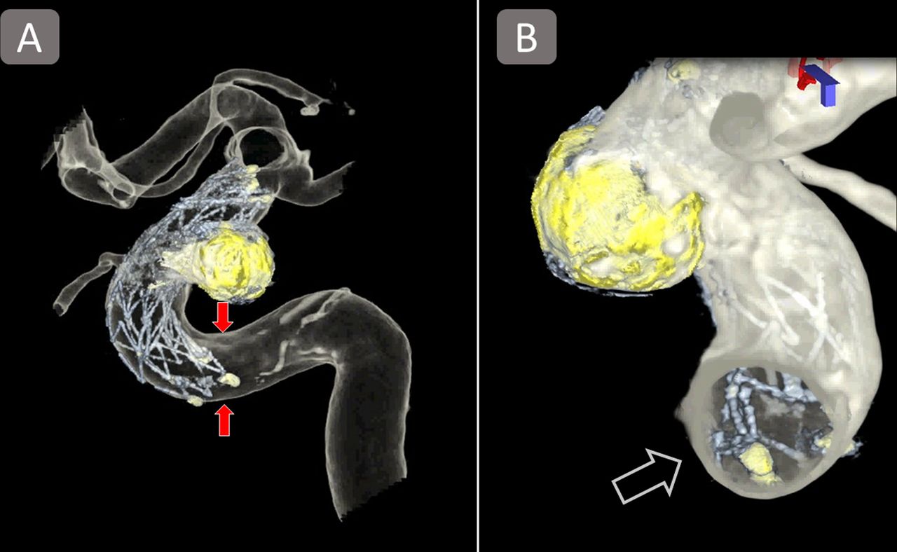
VR images of the aneurysm treated with Neuroform stent (case 1). The VR images visualise the three-dimensional contours of the stent and its apposition in the treated vessel (A). Despite an excellent apposition on its distal side, the proximal side of the stent showed prominent malapposition (arrows). Endoscopic view (B) also showed a segment of the stent struts placed across the vessel lumen (blank arrow). VR, volume rendering.
Case 2: left ICA aneurysm treated with coil embolisation using a Neuroform stent
Figure 2 shows the images of a 42-year-old man who underwent endovascular treatment for the incidentally found unruptured multiple aneurysms including irregular shaped left ICA ophthalmic artery aneurysm. The decision was made to treat the largest aneurysm with stent-assisted coil embolisation as the first step of the treatment. A 4.0×20 Neuroform EZ stent was deployed at the left carotid siphon, and coiling was performed using a total of eight target coils (Stryker Corporation) with a VER of 23.7%. The procedure was completed without any adverse events and postprocedure image evaluation was performed.

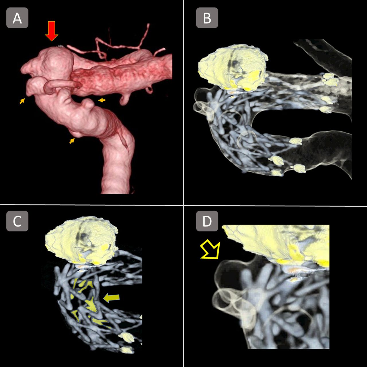
VR images of an aneurysm treated with a Neuroform stent (case 2). (A) A three-dimensional DSA image of an irregular shaped ICA/ophthalmic artery aneurysm accompanied by multiple small aneurysms of the carotid siphon. The largest aneurysm (red arrow) was first treated with a Neuroform stent. (B) The Volume Rendering Technique (VRT) reconstruction of the combined image showed excellent apposition of both proximal and distal ends. (C) However, the struts highlighted with the yellow colour (yellow arrow) indicate inward prolapse of the stent struts, which was not captured in the conventional two-dimensional images. (D) A mild protrusion of a stent strut into a small aneurysm near the ophthalmic artery (blank arrow) is also observed. ICA, internal carotid artery.
Image findings
Preprocedural 3D DSA showed an irregularly shaped 6-mm aneurysm located near the origin of the ophthalmic artery, along with a total of four small aneurysms at the carotid siphon (figure 2A). Similar to case 1, VR images of the treated aneurysm allowed for good visualisation of the Neuroform stent, coil mass and the vessel wall (figure 2B). Both the distal and proximal ends of the stent showed good apposition. However, there was a notable inward prolapse of the struts observed at the inner curvature side of the carotid siphon (figure 2C), most likely due to the structural property of the open-cell stent when placed in a curved vessel. The VR images also showed mild protrusion of a stent strut into a small aneurysm near the ophthalmic artery (figure 2D).
Outcome and follow-up
Both patients recovered from the initial treatment with no neurological deficit. Follow-up MRI and magnetic resonance angiography (MRA) were repeated at 3, 6 and 12 months after the treatment, which showed complete occlusion of the aneurysms. Both patients showed no neurological deficit at the office visit for postprocedure 1 year follow-up. Cerebral angiogram performed at 12 months after the treatment showed no recanalisation of the aneurysms and no stent-related stenosis of the treated vessels.
Discussion
Improved visualisation of stent apposition using VR images
It has been reported that the different types of stents show different types of malapposition. Hellar et al reported that the risk of stent malapposition of Enterprise stent (Johnson & Johnson, New Brunswick, New Jersy, USA) was associated with the curvature radius of the carotid siphon as well as the diameter of the target vessel, and it was mitigated by a specific delivering technique.7 8 The conventional imaging technique to evaluate the apposition of deployed stents is to perform CBCT with dilute contrast medium (10%–20%) followed by the reconstruction of thin-slice cross-sectional images or MIP images.9 10 These imaging techniques are, however, not necessarily sufficient to understand the 3D structures of the deployed stent and the treated vessel. Also, the 3D images obtained from the techniques above often have difficulty in differentiating the image of stent device from the vessel image due to the low SNR of the stent devices, which are made of relatively low-radiopacity materials, eg, nitinol or cobalt-chrome. In the present study, we used HR CBCT to optimise visualisation of the deployed stent, because it is known to increase the SNR5 11 12 with improved spatial resolution when compared with conventional CBCT. Furthermore, clear differentiation of the stent and the vessel wall was achieved by performing an independent acquisition for each target structure. Together with the effect of MAR software, 3D configuration of the two target structures was thereby well clarified and differentiated.
Future applications
To prevent postoperative thromboembolic complications associated with intracranial stenting, the dual antiplatelet therapy is widely used in the current clinical practice of endovascular aneurysm treatment. On the other hand, prolonged antiplatelet therapy can increase the risk of haemorrhagic complications. This new imaging technique might contribute to the decision-making on the course of antiplatelet therapy, based on the status of stent apposition. For instance, the imaging results may help us decide to discontinue the antiplatelet therapy earlier for those with excellent stent apposition. Moreover, the importance of stent apposition is even more emphasised when the patients are treated with FD stenting. Intraoperative evaluation of stent apposition using this imaging technique might help operators to determine whether or not the postdeployment in-stent balloon angioplasty needs to be performed to improve its apposition as well.
Limitations of the study
This imaging technique requires fusion of the datasets obtained from two independent acquisitions. Although the fusion processing was performed using a commercially available software which automatically recognises the spatial coordinates of each acquired dataset, and based thereon, matches the two images, the accuracy of the fusion programme has not been validated. Further investigation evaluating the reproducibility/accuracy of the automatic fusion programme is warranted.
Yang et al 13 reported that the vessel measurement on 2D DSA images could provide consistent accuracy when a manual calibration is performed. However, the accurate measurement on the 3D images remains controversial. In our series, an automatic window level adjustment programme was applied to every dataset. The programme seemed to provide consistent measurements as compared with 2D datasets, although, again, further investigation to evaluate its accuracy and reproducibility needs to be performed.
The acquisition protocol presented in this study requires two acquisitions, which could increase the radiation dose to each patient. If the image information from the CBCT can be used as the mask images for the subsequent DSA acquisition, the total radiation dose for this imaging method can be reduced. Further modification of image acquisition programmes may solve this issue.
Learning points
High-resolution cone beam CT, together with three-dimensional (3D) DSA and metal artefact reduction software, provides improved 3D visualisation of the stent devices used for intracranial aneurysm treatment.
A new image fusion application facilitates the visualisation of stent apposition in the 3D images.
Further investigation to evaluate the reproducibility and accuracy of this imaging technique is warranted.
References
Footnotes
Contributors All co-authors contributed to the conception of the work, data collection or analysis, critical revision of the article, and the final approval of the manuscript although each of them had more commitment to particular work than others as follows. IY conceived the design of the work, performed data collection, and its interpretation. He also drafted the article and made a critical revision of the article. TI helped data collection, clinical analysis, its interpretation, and provided the final approval of the manuscript. CD and KO helped data analysis, particularly in the technical aspect of the angiosystem and image reconstruction process. NK, AI, help data collection, its interpretation, and provided final approval. YA, TK, IK, and KN, contributed data collection, clinical interpretation, and critical revision of the article. YM contributed conception of the work, critical revision, and the final approval of the article.
Funding This study was partially funded by the Siemens Research Grant.
Competing interests None declared.
Provenance and peer review Not commissioned; externally peer reviewed.
Patient consent for publication Obtained.